The mammalian ear can be divided into three main parts: the outer ear, middle ear, and inner ear, all of which are required for effective hearing.
Normal ear and its evaluation
Author: Ian Suchet1, Janelle Santos2
1. Ian Suchet MBBCh FRCPC, Calgary MFM Centre, EFW Radiology, Calgary, Alberta Canada
2. Mayo Clinic, Department of Obstetrics and Gynecology, Rochester, MN, USA
Reviewers: Karen Fung-Kee-Fung, Mauro Schenone
Imaging of the fetal ear
Imaging modalities that evaluate the fetal ear include:
- 2D ultrasound.
- 3D ultrasound.
- MRI of the fetal face and temporal bone.
Ultrasound
Ear anomalies, although frequently encountered in many syndromes, has received little attention in the ultrasound literature due to several factors that include:
- Visualization of the fetal ear is not part of the routine assessment of the fetus, and therefore isolated ear anomalies are generally missed. Ears are more frequently evaluated when other anomalies present.
- Evaluation of ear location and morphology usually requires 3D imaging as they are more difficult to evaluate on 2D imaging.
- Fetal position and more advanced gestational age make it difficult to image both ears.
- Asymmetry of ear anomalies are common, therefore, each ear must be evaluated separately.
- Very few syndromes have a pathognomonic ear shape. Due to this lack of specificity, evaluation of the ear alone, does not alone make the diagnosis of a syndrome, rather it helps to confirm a syndrome when other more classical sonographic signs are present.
The advantages of assessing the fetal ear include:
- Unambiguous findings of an abnormality as the anatomy of the human ear is constant and not ethnically dependent.
- Assessment of ear size, shape, morphology, and location on the fetal face can be obtained.
- Confirmation of a syndrome based on the presence of an abnormal ear.
A retrospective study in Sweden revealed that no ear abnormalities were detected on routine ultrasound, although the prevalence of minor ear abnormalities was 2.4 per 1000 and major ear malformations of 0.3 per 1000 (1).
Shih and colleagues obtained adequate images of the fetal ears in 84% of cases when utilizing 3D ultrasound (2).
Chang and coworkers (3) determined that 3D ultrasound was superior to 2D ultrasound given that 3D ultrasound allowed for the evaluation of ear shape in 93% of cases versus only 40% with 2D ultrasound (3).
First trimester ultrasound
The ear has been extensively evaluated in the first trimester. Ear size can be measured (Figure 3), however, morphology of the auricle cannot be evaluated at this early GA. Ear location cannot be evaluated due to progressive superior migration and rotation of the auricle with advancing gestational age.
Sacchini and coworkers (4) measured fetal ear length at 11-14 weeks of gestation while screening for chromosomal defects. The fetal ear length was measured in 450 fetuses immediately before chorionic villus sampling for karyotyping at 11-14 weeks of gestation. The fetal ear was successfully examined in all cases. The fetal karyotype was normal in 409 cases and abnormal in 41, including 32 cases of trisomy 21. In the chromosomally normal group, the fetal ear length increased with crown-rump length from a mean of 3.7 mm at 45 mm to 6.9 mm at 84 mm (Table 1).
Table 1. Reference range (mean, 5th and 95th centiles) of ear length against crown–rump length in chromosomally normal fetuses at 11–14 weeks of gestation (4).
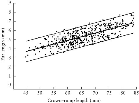
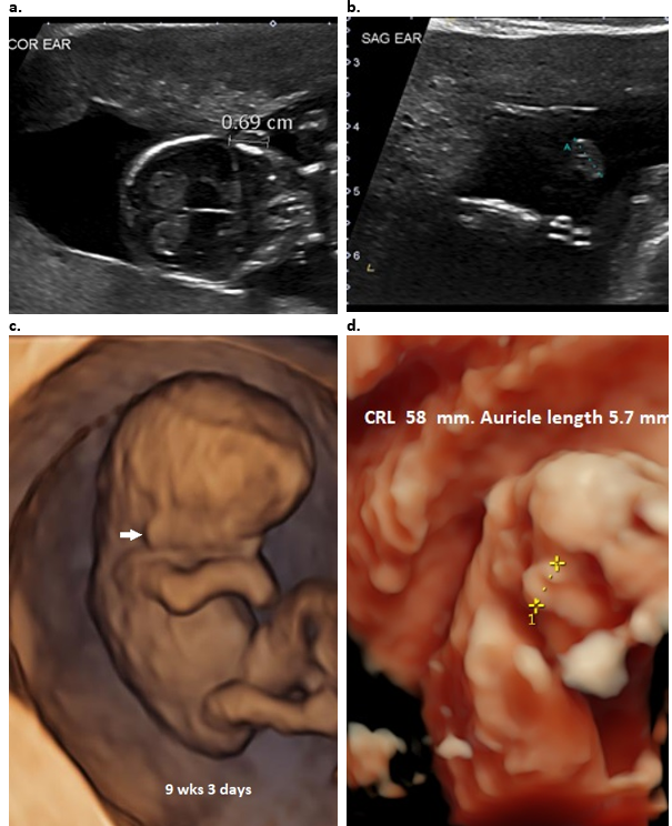
Figure 3: First trimester evaluation of the normal fetal ear.
a. Coronal plane (13+6 6 wks GA). Ear length can be measured in this view.
b. Sagittal plane in a normal fetus (13+6 wks GA). Ear length can be measured however location and morphology cannot be evaluated.
c. 9+3 wks – 3D surface rendered view demonstrates the low location of ear (closed arrow) due to current GA.
d. 3D surface rendered view demonstrates normal ear size at 12 wks GA
Second and Third trimester ultrasound
A. 2D Ultrasound:
The ears are more difficult to evaluate on 2D ultrasound and therefore not routinely imaged.
The ears can be evaluated in all three planes which confer different information.
Axial / transverse plane – The outer ear should be visible in the same transverse plane as the orbits. Each ear is usually evaluated separately as we have found it extremely difficult to obtain both ears and orbits on the same transverse image (Figure 4 a). Care must be taken to avoid angling the scanning plane inferiorly as low set ears will be demonstrated in the same plane as the orbits and falsely suggest that they are normally located. The major axis of the ear is vertical and parallel to the head (Figure 4b). This view can also be used for evaluating ear protrusion but cannot be used to evaluate anatomy of the auricle. The ear length cannot be measured in this plane, however ear width (Figure 4c) can be measured.
Coronal plane – Anatomy of the pinna cannot be evaluated in the coronal plane, however, measurement of ear length and location on the face can be evaluated in this plane (Figure 4d).
Sagittal plane – Outer ear morphology is best visualized in the sagittal plane (Figure 5a). The helix and lobe are always well visualized. The tragus and EAC are more difficult to visualize. The full length of the antihelix can be visualized by subtle probe manipulation into an oblique sagittal view (Figure 5b). The location of the ear on the face cannot be evaluated, however ear width and length can be measured in this plane.
Figure 4: 2D images through the auricle.
- A true transverse / axial image without rotation. Both orbits are imaged (closed arrow). Both ears (open arrows) are difficult to delineate without rotation of the head, however they are located at the level of the orbits.
- Transverse plane with rotation of the head for ear location. Only left ear (open arrows) can be visualized and is at the same level as the orbits (closed arrows). The right orbit is visualized, however the contralateral right ear is not visualized.
- Transverse plane. The width of the ear can be measured from anterior to posterior.
- Coronal image through the auricle – the ear length can be measured from superior helix to inferior portion of the lobe.
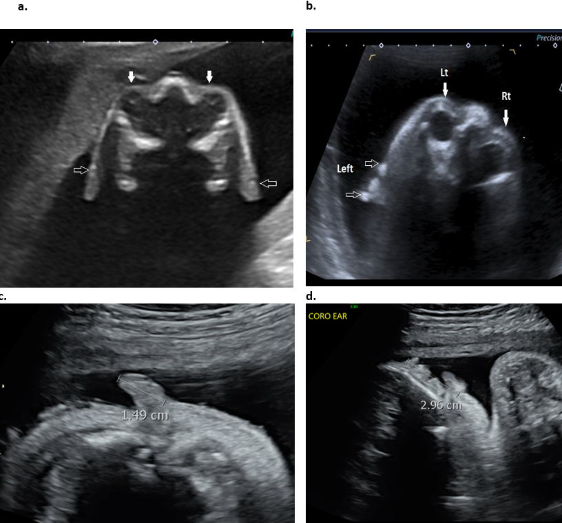
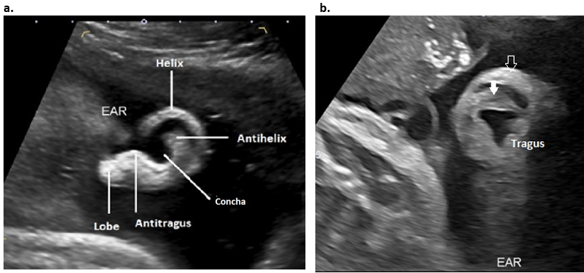
Figure 5: 2D Sagittal plane through the auricle.
- Surface anatomy of the ear. The entire helix, the lobe, the stem of the antihelix and antitragus are visualized in this plane, however the superior and inferior branches of the antihelix and tragus are not visualized.
- Rotation of the image into an oblique plane is necessary to visualize the full length of the antihelix (closed arrow) and tragus. The open arrow represents the superior helix.
B. 3D ultrasound:
3D ultrasound has been shown to be useful in the differentiation between normal and abnormal fetal anatomy (1,2). There are several publications that have evaluated the fetal ear using 3D ultrasound (1-6). Results show that 3D ultrasound reduces the limitations of 2D ultrasound (3) and offers an excellent screening mode for ear malformations and associated disease. 3D ultrasound offers far better visualization and more accurate evaluation of the size, location and anatomy of the auricle.
The ears are best examined at 18-25 wks of gestation when they are easy to identify as they are surrounded by more abundant amniotic fluid. Amniotic fluid must be present surrounding the ear in order to obtain and adequate 3D surface rendered images.
After the ear is identified on 2D imaging, the 3D volume is acquired in either a coronal or transverse plane (Figure 6). The reconstructed volume is rotated until the ear is visualized in a sagittal plane. The sagittal plane enables visualization of the profile of the face and by widening the render box, the entire face and auricle is visible on the same image. Rotation of the ear along its x- and y-axes enables one to better demonstrate facial and ear anatomy and the degree of protrusion of the ear in the coronal and transverse planes.
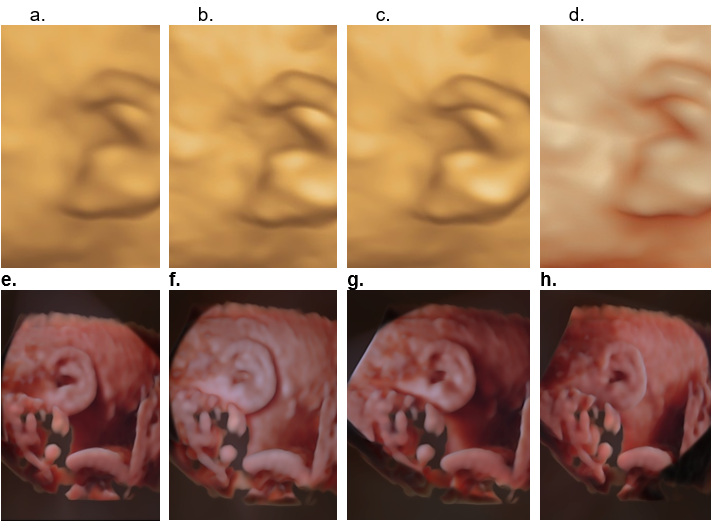
Most of the major improvements in ultrasound in the last few years have come from the use of high-frequency transducers and the advent HD live technology. There are different 3D surface display modes that are available for assessing outer ear morphology (Figure 7 a-d). All are considered satisfactory, however some demonstrate improved visualization of surface anatomy. The HD live surface mode (GE Medical Systems) shows consistent superiority over the other surface display modes. This improvement is acquired by applying an artificial light source to the rendered image that exposes more anatomical detail. This light source is flexible allowing the user to manipulate the light and highlight the anatomical structure of interest. This 3D rendering method takes advantage of “shadowing effects” to improve the visualization of details on the image. This technique uses a virtual light source and reflects the light off the skin surface rather than a fixed light source in conventional 3D surface rendering, HD live rendering calculates the propagation of light through the skin and the tissue creating shadows where light has moved through denser tissues. The virtual light source can be changed and directed easily from any angle and can be manipulated to enhance visualization of tissue structures, define precise outlines and highlight important clinical details (Figure 7 e-h). This tool is especially valuable when evaluating surfaces, especially the facial area. By changing the angle of virtual light, one can adjust it perfectly to emphasize and get depth perception in visualizing a region of interest that may be an anomaly. A translucent effect is gained if the light source is placed behind the object (5). The effect results in more “lifelike” images.
Other workers have shown superiority using a similar display mode called “TrueVue” (Philips Medical Systems).
Other 3D modalities that can be used to evaluate the outer ear include multiplanar reformat images (MPR) and volume contrast imaging (VCI).
Figure 6. MPR and surface rendered 3D image of the fetal right ear. The original acquisition plane was coronal resulting in the 3D plane being demonstrated in a sagittal plane. The solid arrow represents the location of the render dot that demonstrates a periarticular tag in all planes. The open arrows represent the green render line.
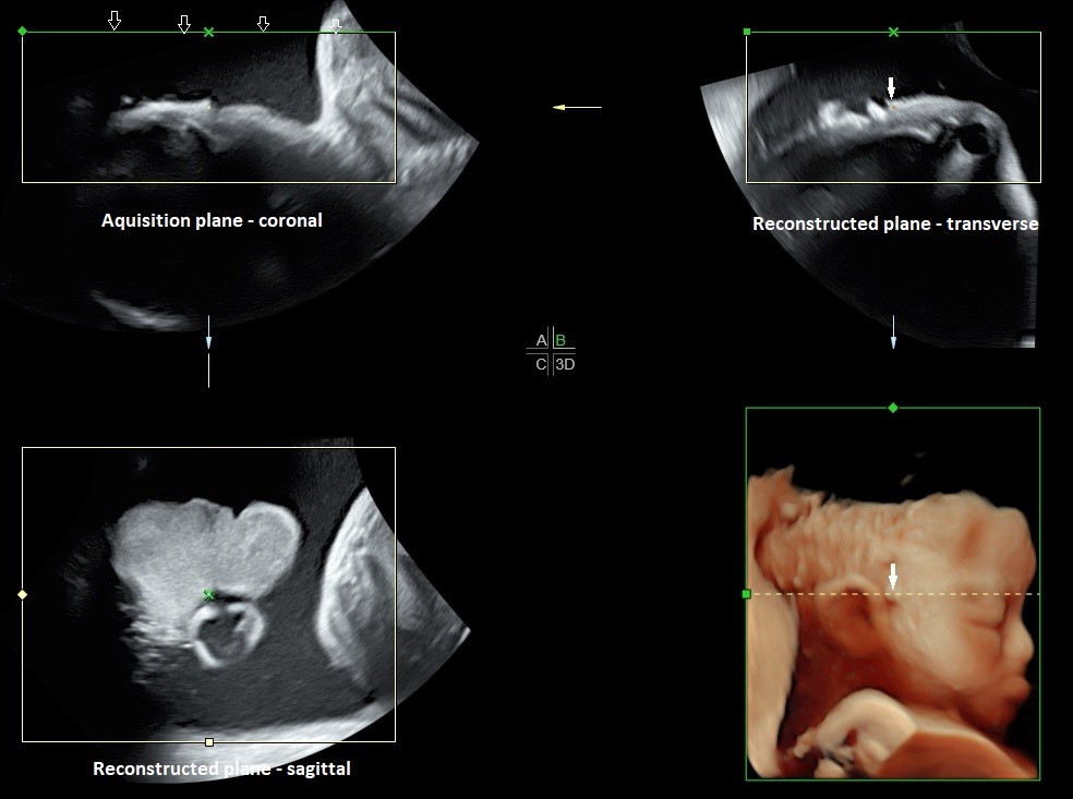
Figure 7. Different surface rendered modes for evaluating the auricle.
- Surface mode - The surface is displayed in “texture” mode. The gray values of the surface are identical with the gray values of the original scan.
- Surface smooth mode - The surface is displayed “smoothed” in “texture” mode.
- Surface enhanced mode - This requires HD rendering. The surface display is improved by homogenous smoothing while details are retained in the image.
- HD live surface mode - HD Live allows one to generate realistic life like images of the ear using an advanced illumination model. HD Live supports shadows, using a virtual light source and advanced skin rendering techniques. By highlighting structures from the side the 3D impression is improved and the surface does not appear flat anymore.
e-h. HD live evaluation of the auricle with different positioning of the virtual light (white arrow delineates position of the virtual light). By moving the light source, different areas of the ear are highlighted.
Advantages of 3D over 2D (2)
- 3D offers clearer visualization of anatomy especially the helix, the tragus and antitragus.
- Spatial information (location, axis orientation) can only be obtained with 3D
- Clearer observation of ear anomalies increases the threshold of suspicion of other organ anomalies which may have gone unnoticed.
- Unfavourable location of fetal position may make visualization with 2D impossible and can only be visualized by 3D.
Both the left and right auricles must both be evaluated separately as unilateral or asymmetrical abnormalities may be present (e.g. unilateral Microtia, OAV spectrum / Goldenhar syndrome).
The auricle is best visualized in the sagittal plane. The anatomy that can be evaluated on sagittal images include:
- Size of the auricle
- Shape / morphology of the auricle
- Level of insertion of the auricle
- Evaluation of the angle of the auricle for assessment of auricular protrusion requires the volume to be rotated into a coronal plane (Figure 8). The 3D volume is rotated 90 degrees to the sagittal plane to assess the ear in a PA (posterior-anterior) plane.
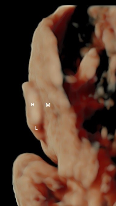
Figure 8: 3D surface rendered view of the normally orientated fetal auricle in an AP plane. Note the normal close approximation of the helix (H) and lobe (L) of the auricle to the mastoid region (M) of the skull with no measurable auriculocephalic angle. This close arrangement obscures the actual site of attachment of the ear to the skull.
External auditory canal and meatus (EAC and EAM)
The EAC is only visualized after 28 wks once involution of ectodermal plug has occurred. It is fluid filled (amniotic fluid) and reportedly seen in only 59% of normal fetuses (Figure 2 d,e). By the 16th week of embryological development, the contour of the external ear is basically formed. By the 26th week, the external auditory canal can reach one-third of its full length. The EAC rises upward and laterally nearly parallel to the tympanic ring. It reaches its auricular opening, the EAM at the lower border of the squamous temporal bone.
Middle ear and inner ear
Middle ear
The tympanic rings are round oval echogenic structures in a plane tangential to the inferolateral surface of the fetal skull below the inferior border of the squamous portion of the temporal bone (8). The tympanic ring is an incomplete bony ring due to the tympanic notch that is present in the lateral margin. Visualization of the tympanic rings can be achieved with both 2D and 3D sonography (using multiplanar reconstruction; Figure 9 d). Leibovitz and coworkers (8) elegantly describe the embryology, anatomy and sonographic technique for their demonstration. Ossification of the rings are complete by 19 weeks of gestation when they reach an internal diameter of 7.5 mm (9). Visualization was best in the early second trimester (16 wks) as echogenic structures superimposed on a hypoechoic cartilaginous petrous ring background.
Inner ear (7). 2D and 3D US can readily evaluate the auricle, however, sonographic evaluation of the temporal bone is more challenging.
Identification of the fetal cochlea caudal to the temporal lobes via US can be obtained in approximately 50% of cases in the second trimester using the fetal anterior fontanelle and coronal plane insonation.
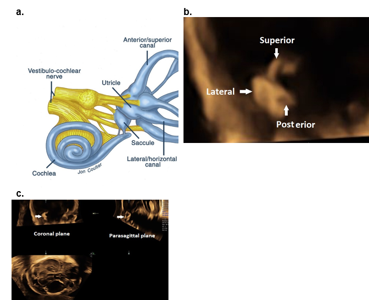
The semicircular canals (Figure 9 a-c) may be identified by second-trimester ultrasound, although with limited resolution.
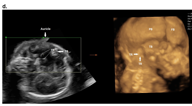
Figure 9. The middle and inner ear.
a-c Inner ear.
a. Schematic illustration of the inner ear.
b. Coronal plane MPR image of the superior, posterior, and lateral semicircular canals.
c. MPR of the semicircular canals in a coronal and parasagittal plane.
d. Middle ear.
The tympanic ring and auricles at 18 weeks of gestation obtained from a single volume acquisition after rotating the volume. The 3D rendered image is displayed in a maximal mode. TR – tympanic ring; TB – squamous portion of the temporal bone; PB – parietal bone; FB – frontal bone.
References
- Romosan G, Henriksson E, Rylander A et.al. Diagnostic performance of routine ultrasound screening for fetal abnormalities in an unselected Swedish population in 2000-2005. Ultrasound Obstet Gynecol 2009;34:526-533.
- Shih JC, Shyu MK, Lee CN et.al. Antenatal depiction of the fetal ear with three-dimensional ultrasonography. Obstet Gynecol,1998; 91(4):500-5
- Chang CH, Chang F M, Yu CH et.al. Fetal ear assessment and prenatal detection of aneuploidy by the quantitative three-dimensional ultrasonography. Ultrasound in Medicine and Biology, 2000; 26(5):743–749.
- Sacchini C, El-Sheikhah A, Cicero S et.al. Ear length in trisomy 21 fetuses at 11-14 weeks of gestation. UOG 2003;22:460-463
- Benoit B, Levaillant JM. Voluson GE healthcare technology. Available at: www.volusonclub.net. 10 Dec 2016.
- Merz E, Welter C. 2D and 3D Ultrasound in the evaluation of normal and abnormal fetal anatomy in the second and third trimesters in a level III center. Ultraschall Med. 2005;26(1): 9–16.
- Daudruy et.al. OP06.04: US anatomy of the middle and inner ear with high‐frequency probe: a pictorial essay. Ultrasound Obstet Gynecol 2017.
- Leibovitz Z, Egenburg S, Brohnshtein M et.al Sonographic imaging of the fetal tympanic rings. Ultrasound Obstet Gynecol 2013;42:536-544.
- Anson BJ, Hanson JS, Richany SF. Early embryology of the auditory ossicles and associated structures in relation to certain anomalies observed clinically. Ann Oto Rhinol Laryngol 1960;69:427-447.
This article should be cited as Suchet I, Santos J: Normal ear and its evaluation. Visual Encyclopedia of Ultrasound in Obstetrics and Gynecology, www.isuog.org, June 2023.
Leave feedback or submit an image
We rely on your feedback to update and improve VISUOG. Please use the form below to submit any comments or feedback you have on this chapter.
If you have any images that you think would make a good addition to this chapter, please also submit them below - you will be fully credited for all images used.
Feedback form
Please note that the maximum upload size is 5MB, and larger images and video clips can be sent to [email protected].